repl.it linkWeek 12 [Nov 4] - Topics
- [W12.1] Other UML Models
-
[W12.1a] Design → Modelling → Modelling Structure → Object Oriented Domain Models
-
[W12.1b] Design → Modelling → Modelling Structure → Deployment Diagrams
-
[W12.1c] Design → Modelling → Modelling Structure → Component Diagrams
-
[W12.1d] Design → Modelling → Modelling Structure → Package Diagrams
-
[W12.1e] Design → Modelling → Modelling Structure → Composite Structure Diagrams
-
[W12.1f] Design → Modelling → Modelling Behaviors Activity Diagrams - Basic
-
[W12.1g] Design → Modelling → Modelling Behaviors Timing Diagrams
-
[W12.1h] Design → Modelling → Modelling Behaviors Interaction Overview Diagrams
-
[W12.1i] Design → Modelling → Modelling Behaviors Communication Diagrams
-
[W12.1j] Design → Modelling → Modelling Behaviors State Machine Diagrams
- [W12.2] Reuse
Intro
-
[W12.2a] Implementation → Reuse → Introduction → What
-
[W12.2b] Implementation → Reuse → Introduction → When
APIs
- [W12.2c] Implementation → Reuse → APIs → What
Libraries
-
[W12.2d] Implementation → Reuse → Libraries → What
-
[W12.2e] Implementation → Reuse → Libraries → How
Frameworks
-
[W12.2f] Implementation → Reuse → Frameworks → What
-
[W12.2g] Implementation → Reuse → Frameworks → Frameworks vs Libraries
Platforms
- [W12.2h] Implementation → Reuse → Platforms → What
- [W12.3] Quality Assurance
-
[W12.3a] Quality Assurance → Quality Assurance → Introduction → What
-
[W12.3b] Quality Assurance → Quality Assurance → Introduction → Validation vs Verification
-
[W12.3c] Quality Assurance → Quality Assurance → Code Reviews → What
-
[W12.3d] Quality Assurance → Quality Assurance → Static Analysis → What
-
[W12.3e] Quality Assurance → Quality Assurance → Formal Verification → What
Design → Modelling → Modelling Structure → Object Oriented Domain Models
Can explain object oriented domain models
The analysis process for identifying objects and object classes is recognized as one of the most difficult areas of object-oriented development. --Ian Sommerville, in the book Software Engineering
Class diagrams can also be used to model objects in the
OO domain model of a snakes and ladders game is given below.
Description: Snakes and ladders game is played by two or more players using a board and a die. The board has 100 squares marked 1 to 100. Each player owns one piece. Players take turns to throw the die and advance their piece by the number of squares they earned from the die throw. The board has a number of snakes. If a player’s piece lands on a square with a snake head, the piece is automatically moved to the square containing the snake’s tail. Similarly, a piece can automatically move from a ladder foot to the ladder top. The player whose piece is the first to reach the 100th square wins.
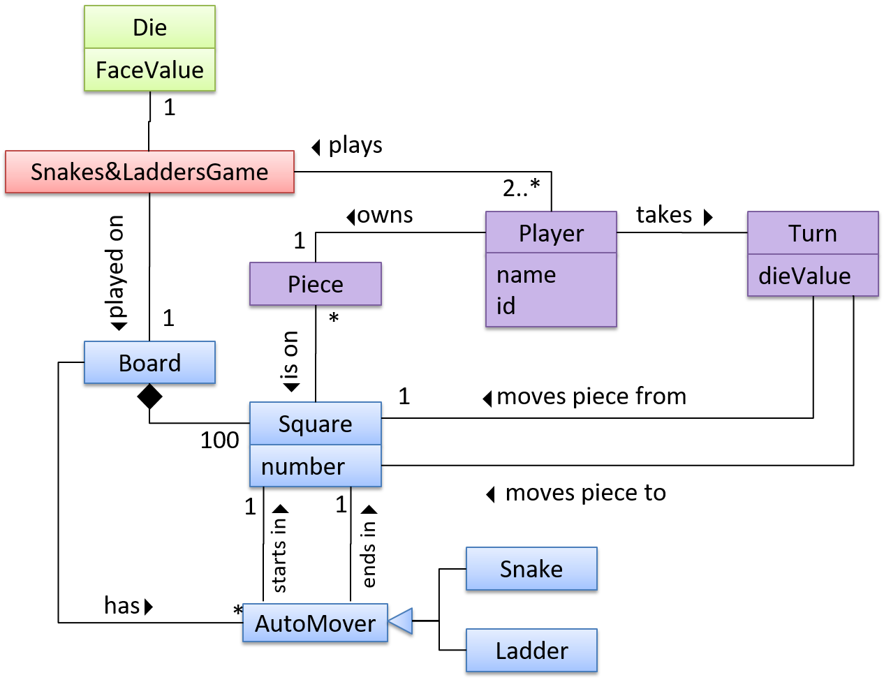
The above OO domain model omits the ladder class for simplicity. It can be included in a similar fashion to the Snake class.
OODMs do not contain solution-specific classes (i.e. classes that are used in the solution domain but do not exist in the problem domain). For example, a class called DatabaseConnection could appear in a class diagram but not usually in an OO domain model because DatabaseConnection is something related to a software solution but not an entity in the problem domain.
OODMs represents the class structure of the problem domain and not their behavior, just like class diagrams. To show behavior, use other diagrams such as sequence diagrams.
OODM notation is similar to class diagram notation but omit methods and navigability.
This diagram is,
- a. A class diagram.
- b. An object diagram.
- c. An OO domain model, also known as a conceptual class diagram.
- d. Can be either a class diagram or an OO domain model.
(a)
Explanation: The diagram shows navigability which is not shown in an OO domain model. Hence, it has to be a class diagram.
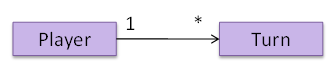
What is the main difference between a class diagram and and an OO domain model?
(a)
Explanation: Both are UML diagrams, and use the class diagram notation. While it is true that often a class diagram may have more classes and more details, the main difference is that the OO domain model describes the problem domain while the class diagram describes the solution.
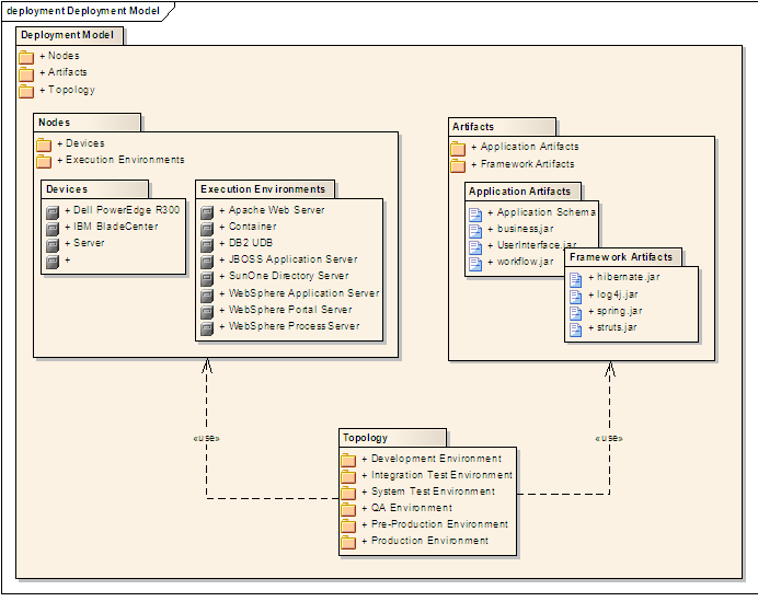
Design → Modelling → Modelling Structure → Deployment Diagrams
Can explain deployment diagrams
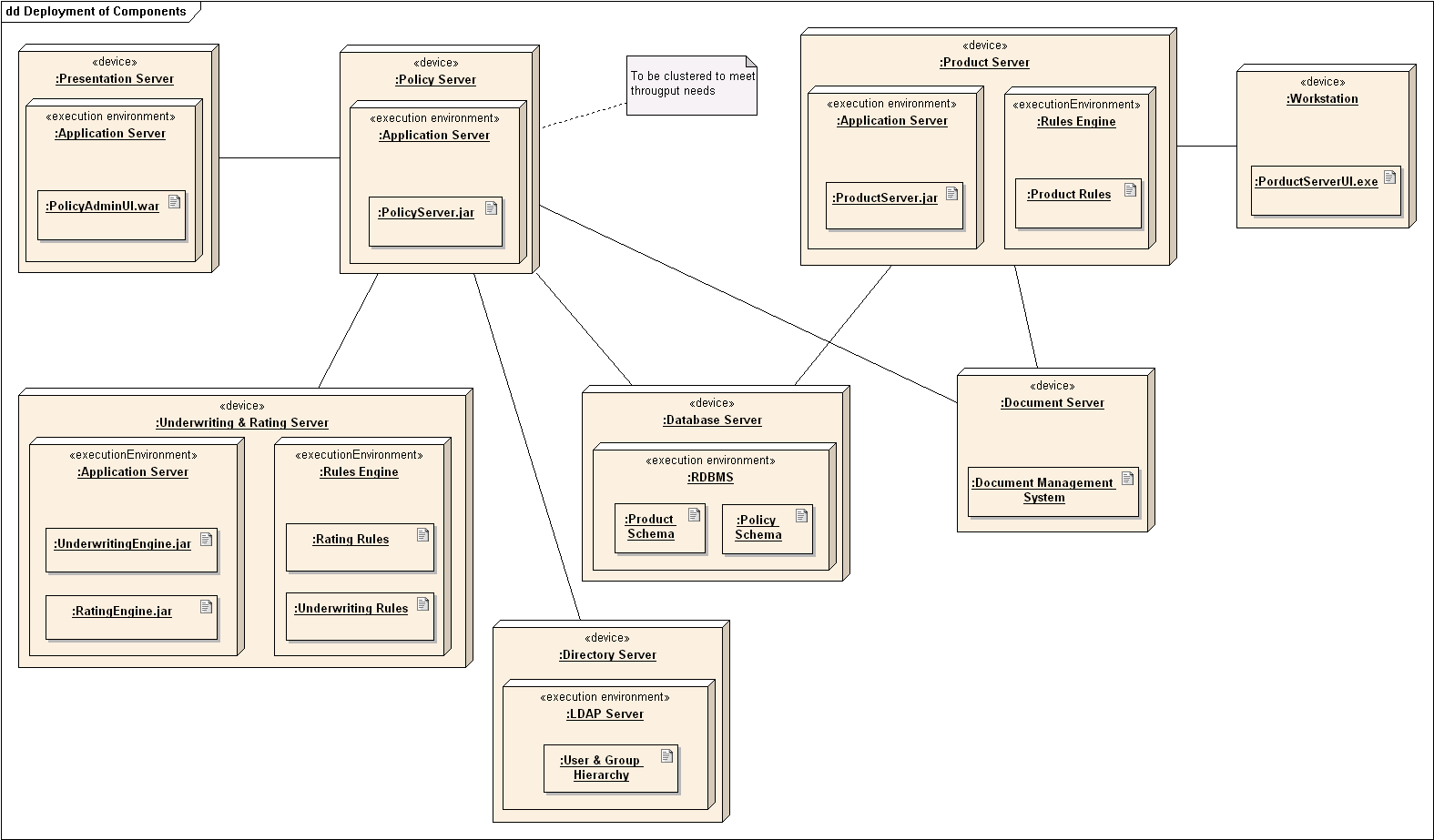
A deployment diagram shows a system's physical layout, revealing which pieces of software run on which pieces of hardware.
An example deployment diagram:
Design → Modelling → Modelling Structure → Component Diagrams
Can explain component diagrams
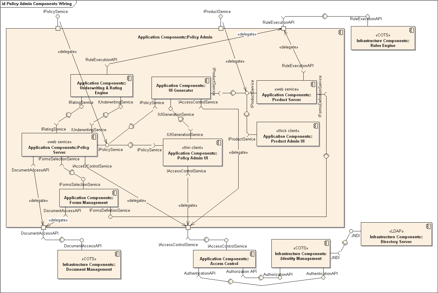
A component diagram is used to show how a system is divided into components and how they are connected to each other through interfaces.
An example component diagram:
Design → Modelling → Modelling Structure → Package Diagrams
Can explain package diagrams
A package diagram shows packages and their dependencies. A package is a grouping construct for grouping UML elements (classes, use cases, etc.).
Here is an example package diagram:
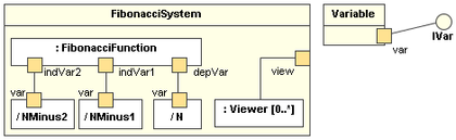
Design → Modelling → Modelling Structure → Composite Structure Diagrams
Can explain composite structure diagrams
A composite structure diagram hierarchically decomposes a class into its internal structure.
Here is an example composite structure diagram:
Design → Modelling → Modelling Behaviors Activity Diagrams - Basic
Can use basic-level activity diagrams
Software projects often involve workflows. Workflows define the
Some examples in which a certain workflow is relevant to software project:
A software that automates the work of an insurance company needs to take into account the workflow of processing an insurance claim.
The algorithm of a price of code represents the workflow (i.e. the execution flow) of the code.
Which of these sequence of actions is not allowed by the given activity diagram?
- i. start a b c d end
- ii. start a b c d e f g c d end
- iii. start a b c d e g f c d end
- iv. start a b c d g c d end
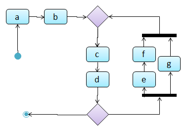
(iv)
Explanation: -e-f- and -g- are parallel paths. Both paths should complete before the execution reaches c again.
Draw an activity diagram to represent the following workflow a burger shop uses when processing an order by a customer.
- First, a cashier takes the order.
- Then, three workers start preparing the order at the same time; one prepares the drinks, one prepares the burgers, and one prepares the desserts.
- In the meantime, the customer pays for the order. If the customer has a voucher, she pays using the voucher; otherwise she pays using cash.
- After paying, the customer collects the food after all three parts of the order are ready.

Design → Modelling → Modelling Behaviors Timing Diagrams
Can explain timing diagrams
A timing diagram focus on timing constraints.
Here is an example timing diagram:
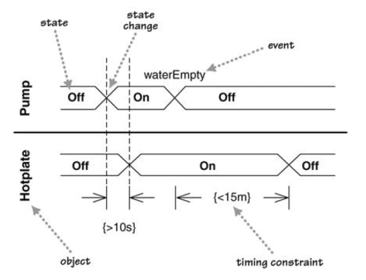
Adapted from: UML Distilled by Martin Fowler
Design → Modelling → Modelling Behaviors Interaction Overview Diagrams
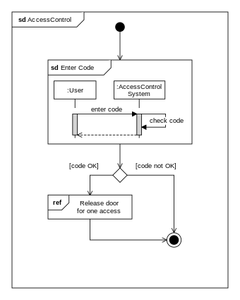
Can explain interaction overview diagrams
An Interaction overview diagrams is a combination of activity diagrams and sequence diagrams.
An example:
Design → Modelling → Modelling Behaviors Communication Diagrams
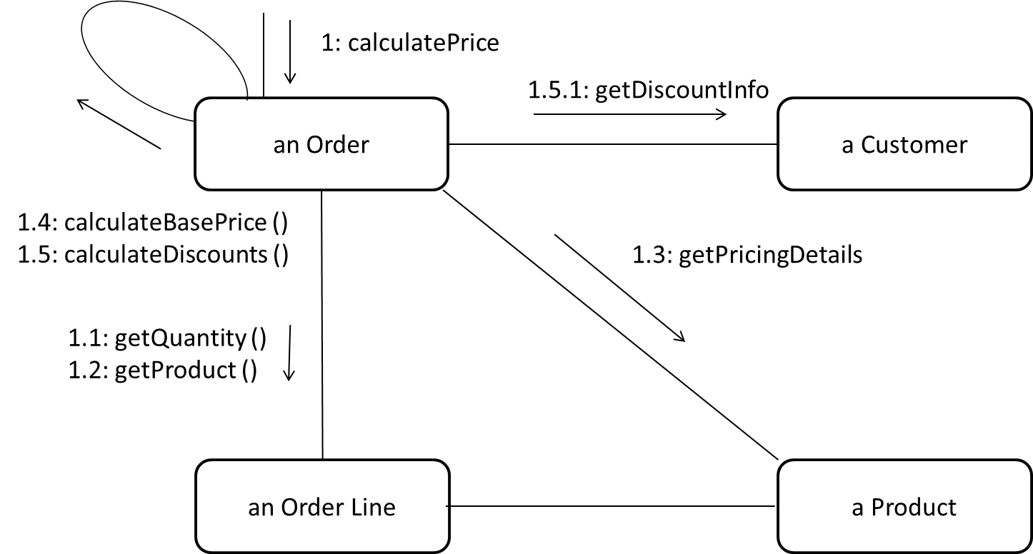
Can explain communication diagrams
A Communication diagrams are like sequence diagrams but emphasize the data links between the various participants in the interaction rather than the sequence of interactions.
An example:
Adapted from: UML Distilled by Martin Fowler
Design → Modelling → Modelling Behaviors State Machine Diagrams
Can explain state machine diagrams
A State Machine Diagram models state-dependent behavior.
Consider how a CD player responds when the “eject CD” button is pushed:
- If the CD tray is already open, it does nothing.
- If the CD tray is already in the process of opening (opened half-way), it continues to open the CD tray.
- If the CD tray is closed and the CD is being played, it stops playing and opens the CD tray.
- If the CD tray is closed and CD is not being played, it simply opens the CD tray.
- If the CD tray is already in the process of closing (closed half-way), it waits until the CD tray is fully closed and opens it immediately afterwards.
What this means is that the CD player’s response to pushing the “eject CD” button depends on what it was doing at the time of the event. More generally, the CD player’s response to the event received depends on its internal state. Such a behavior is called a state-dependent behavior.
Often, state-dependent behavior displayed by an object in a system is simple enough that it needs no extra attention; such a behavior can be as simple as a conditional behavior like if x>y, then x=x-y.
Occasionally, objects may exhibit state-dependent behavior that is complex enough such that it needs to be captured into a separate model. Such state-dependent behavior can be modelled using UML state machine diagrams (SMD for short, sometimes also called ‘state charts’, ‘state diagrams’ or ‘state machines’).
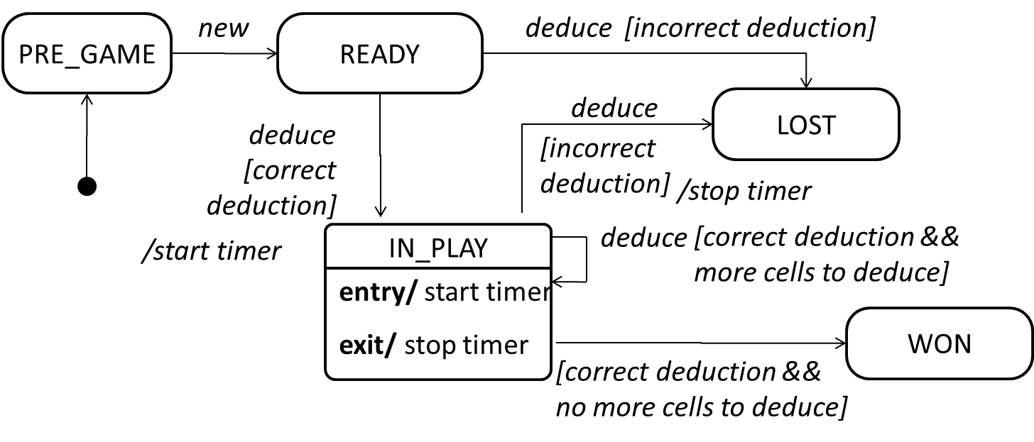
An SMD views the life-cycle of an object as consisting of a finite number of states where each state displays a unique behavior pattern. An SMD captures information such as the states an object can be in, during its lifetime, and how the object responds to various events while in each state and how the object transits from one state to another. In contrast to sequence diagrams that capture object behavior one scenario at a time, SMDs capture the object’s behavior over its full life cycle.
An SMD for the Minesweeper game.
Intro
Implementation → Reuse → Introduction → What
Can explain software reuse
Reuse is a major theme in software engineering practices. By reusing tried-and-tested components, the robustness of a new software system can be enhanced while reducing the manpower and time requirement. Reusable components come in many forms; it can be reusing a piece of code, a subsystem, or a whole software.
Implementation → Reuse → Introduction → When
Can explain the costs and benefits of reuse
While you may be tempted to use many libraries/frameworks/platform that seem to crop up on a regular basis and promise to bring great benefits, note that there are costs associated with reuse. Here are some:
- The reused code may be an overkill (think using a sledgehammer to crack a nut) increasing the size of, or/and degrading the performance of, your software.
- The reused software may not be mature/stable enough to be used in an important product. That means the software can change drastically and rapidly, possibly in ways that break your software.
- Non-mature software has the risk of dying off as fast as they emerged, leaving you with a dependency that is no longer maintained.
- The license of the reused software (or its dependencies) restrict how you can use/develop your software.
- The reused software might have bugs, missing features, or security vulnerabilities that are important to your product but not so important to the maintainers of that software, which means those flaws will not get fixed as fast as you need them to.
- Malicious code can sneak into your product via compromised dependencies.
One of your teammates is proposing to use a recently-released “cool” UI framework for your class project. List the pros and cons of this idea.
Pros
- The potential to create a much better product by reusing the framework.
- Learning a new framework is good for the future job prospects.
Cons
- Learning curve may be steep.
- May not be stable (it was recently released).
- May not allow us to do exactly what we want. While frameworks allow customization, such customization can be limited.
- Performance penalties.
- Might interfere with learning objectives of the module.
Note that having more cons does not mean we should not use this framework. Further investigation is required before we can make a final decision.
APIs
Implementation → Reuse → APIs → What
Can explain APIs
An Application Programming Interface (API) specifies the interface through which other programs can interact with a software component. It is a contract between the component and its clients.
A class has an API (e.g., API of the Java String class, API of the Python str class) which is a collection of public methods that you can invoke to make use of the class.
The GitHub API is a collection of Web request formats GitHub server accepts and the corresponding responses. We can write a program that interacts with GitHub through that API.
When developing large systems, if you define the API of each components early, the development team can develop the components in parallel because the future behavior of the other components are now more predictable.
Choose the correct statements
- a. A software component can have an API.
- b. Any method of a class is part of its API.
- c. Private methods of a class are not part of its API.
- d. The API forms the contract between the component developer and the component user.
- e. Sequence diagrams can be used to show how components interact with each other via APIs.
(a) (c) (d) (e)
Explanation: (b) is incorrect because private methods cannot be a part of the API
Defining component APIs early is useful for developing components in parallel.
True
Explanation: Yes, once we know the precise behavior expected of each component, we can start developing them in parallel.
Libraries
Implementation → Reuse → Libraries → What
Can explain libraries
A library is a collection of modular code that is general and can be used by other programs.
Java classes you get with the JDK (such as String, ArrayList, HashMap, etc.) are library classes that are provided in the default Java distribution.
Natty is a Java library that can be used for parsing strings that represent dates e.g. The 31st of April in the year 2008
built-in modules you get with Python (such as csv, random, sys, etc.) are libraries that are provided in the default Python distribution. Classes such as list, str, dict are built-in library classes that you get with Python.
Colorama is a Python library that can be used for colorizing text in a CLI.
Implementation → Reuse → Libraries → How
Can make use of a library
These are the typical steps required to use a library.
- Read the documentation to confirm that its functionality fits your needs
- Check the license to confirm that it allows reuse in the way you plan to reuse it. For example, some libraries might allow non-commercial use only.
- Download the library and make it accessible to your project. Alternatively, you can configure your
dependency management tool to do it for you. - Call the library API from your code where you need to use the library functionality.
Frameworks
Implementation → Reuse → Frameworks → What
Can explain frameworks
The overall structure and execution flow of a specific category of software systems can be very similar. The similarity is an opportunity to reuse at a high scale.
Running example:
IDEs for different programming languages are similar in how they support editing code, organizing project files, debugging, etc.
A software framework is a reusable implementation of a software (or part thereof) providing generic functionality that can be selectively customized to produce a specific application.
Running example:
Eclipse is an IDE framework that can be used to create IDEs for different programming languages.
Some frameworks provide a complete implementation of a default behavior which makes them immediately usable.
Running example:
Eclipse is a fully functional Java IDE out-of-the-box.
A framework facilitates the adaptation and customization of some desired functionality.
Running example:
Eclipse plugin system can be used to create an IDE for different programming languages while reusing most of the existing IDE features of Eclipse. E.g. https://marketplace.eclipse.org/content/pydev-python-ide-eclipse
Some frameworks cover only a specific components or an aspect.
JavaFx a framework for creating Java GUIs. TkInter is a GUI framework for Python.
More examples of frameworks
- Frameworks for Web-based applications: Drupal(PHP), Django(Python), Ruby on Rails (Ruby), Spring (Java)
- Frameworks for testing: JUnit (Java), unittest (Python), Jest (Java Script)
Implementation → Reuse → Frameworks → Frameworks vs Libraries
Can differentiate between frameworks and libraries
Although both frameworks and libraries are reuse mechanisms, there are notable differences:
-
Libraries are meant to be used ‘as is’ while frameworks are meant to be customized/extended. e.g., writing plugins for Eclipse so that it can be used as an IDE for different languages (C++, PHP, etc.), adding modules and themes to Drupal, and adding test cases to JUnit.
-
Your code calls the library code while the framework code calls your code. Frameworks use a technique called inversion of control, aka the “Hollywood principle” (i.e. don’t call us, we’ll call you!). That is, you write code that will be called by the framework, e.g. writing test methods that will be called by the JUnit framework. In the case of libraries, your code calls libraries.
Choose correct statements about software frameworks.
- a. They follow the hollywood principle, otherwise known as ‘inversion of control’
- b. They come with full or partial implementation.
- c. They are more concrete than patterns or principles.
- d. They are often configurable.
- e. They are reuse mechanisms.
- f. They are similar to reusable libraries but bigger.
(a)(b)(c)(d)(e)(f)
Explanation: While both libraries and frameworks are reuse mechanisms, and both more concrete than principles and patterns, libraries differ from frameworks in some key ways. One of them is the ‘inversion of control’ used by frameworks but not libraries. Furthermore, frameworks do not have to be bigger than libraries all the time.
Which one of these are frameworks ?
(a)(b)(c)(d)
Explanation: These are frameworks.
Platforms
Implementation → Reuse → Platforms → What
Can explain platforms
A platform provides a runtime environment for applications. A platform is often bundled with various libraries, tools, frameworks, and technologies in addition to a runtime environment but the defining characteristic of a software platform is the presence of a runtime environment.
Technically, an operating system can be called a platform. For example, Windows PC is a platform for desktop applications while iOS is a platform for mobile apps.
Two well-known examples of platforms are JavaEE and .NET, both of which sit above Operating systems layer, and are used to develop
- JavaEE (Java Enterprise Edition) is both a framework and a platform for writing enterprise applications. The runtime used by the JavaEE applications is the JVM (Java Virtual Machine) that can run on different Operating Systems.
- .NET is a similar platform and a framework. Its runtime is called CLR (Common Language Runtime) and usually used on Windows machines.
Enterprise Application: ‘enterprise applications’ means software applications used at organizations level and therefore has to meet much higher demands (such as in scalability, security, performance, and robustness) than software meant for individual use.
Quality Assurance → Quality Assurance → Introduction → What
Can explain software quality assurance
Software Quality Assurance (QA) is the process of ensuring that the software being built has the required levels of quality.
While testing is the most common activity used in QA, there are other complementary techniques such as static analysis, code reviews, and formal verification.
Quality Assurance → Quality Assurance → Introduction → Validation vs Verification
Can explain validation and verification
Quality Assurance = Validation + Verification
QA involves checking two aspects:
- Validation: are we building the right system i.e., are the requirements correct?
- Verification: are we building the system right i.e., are the requirements implemented correctly?
Whether something belongs under validation or verification is not that important. What is more important is both are done, instead of limiting to verification (i.e., remember that the requirements can be wrong too).
Choose the correct statements about validation and verification.
- a. Validation: Are we building the right product?, Verification: Are we building the product right?
- b. It is very important to clearly distinguish between validation and verification.
- c. The important thing about validation and verification is to remember to pay adequate attention to both.
- d. Developer-testing is more about verification than validation.
- e. QA covers both validation and verification.
- f. A system crash is more likely to be a verification failure than a validation failure.
(a)(b)(c)(d)(e)(f)
Explanation:
Whether something belongs under validation or verification is not that important. What is more important is that we do both.
Developer testing is more about bugs in code, rather than bugs in the requirements.
In QA, system testing is more about verification (does the system follow the specification?) and acceptance testings is more about validation (does the system solve the user’s problem?).
A system crash is more likely to be a bug in the code, not in the requirements.
Quality Assurance → Quality Assurance → Code Reviews → What
Can explain code reviews
Code review is the systematic examination code with the intention of finding where the code can be improved.
Reviews can be done in various forms. Some examples below:
-
Pull Request reviews
- Project Management Platforms such as GitHub and BitBucket allow the new code to be proposed as Pull Requests and provide the ability for others to review the code in the PR.
-
In
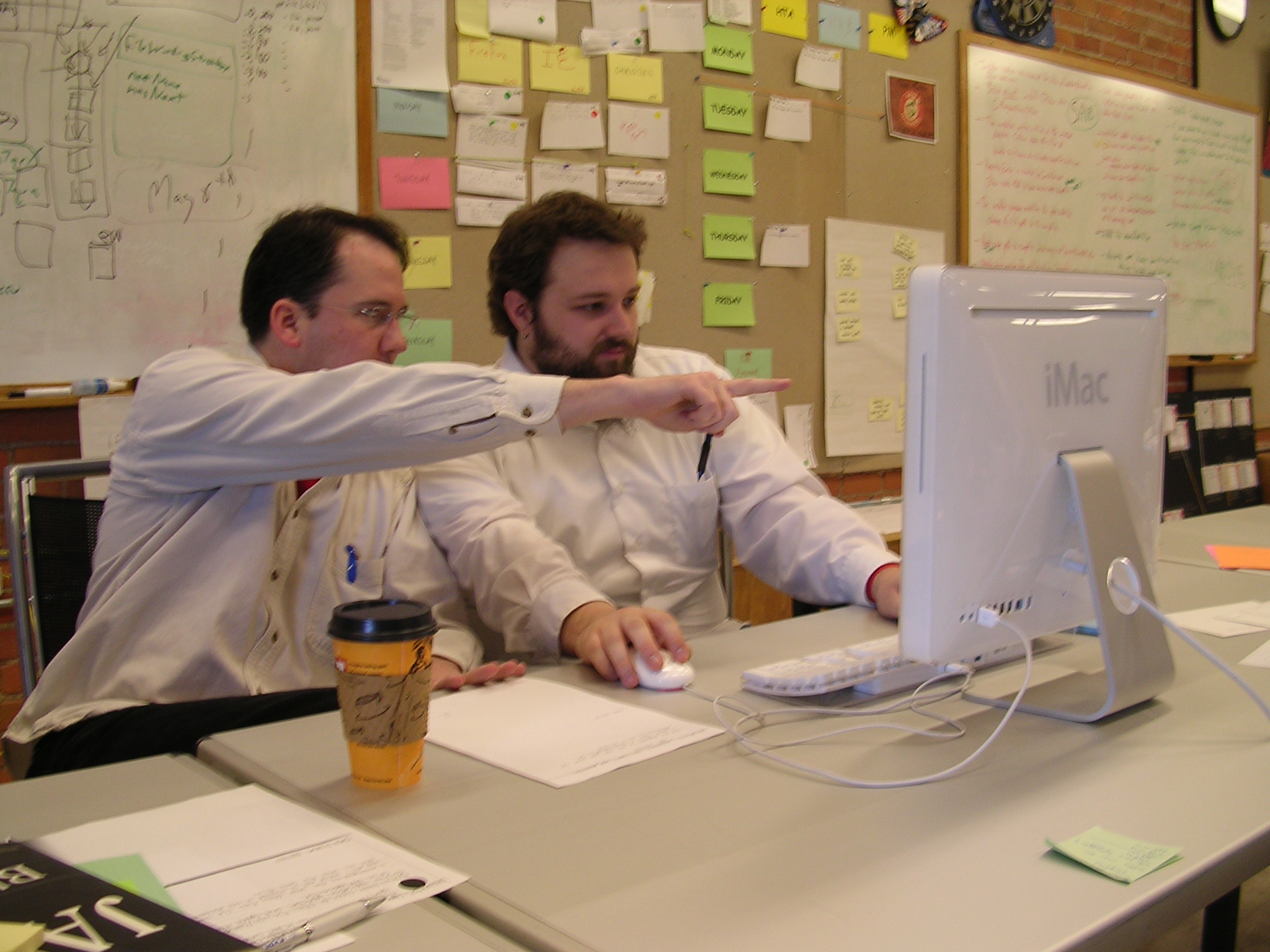
pair programming - As pair programming involves two programmers working on the same code at the same time, there is an implicit review of the code by the other member of the pair.
Pair Programming:
Pair programming is an agile software development technique in which two programmers work together at one workstation. One, the driver, writes code while the other, the observer or navigator, reviews each line of code as it is typed in. The two programmers switch roles frequently. [source: Wikipedia]
A good introduction to pair programming:
-
Formal inspections
-
Inspections involve a group of people systematically examining a project artifacts to discover defects. Members of the inspection team play various roles during the process, such as:
- the author - the creator of the artifact
- the moderator - the planner and executor of the inspection meeting
- the secretary - the recorder of the findings of the inspection
- the inspector/reviewer - the one who inspects/reviews the artifact.
-
Advantages of code reviews over testing:
- It can detect functionality defects as well as other problems such as coding standard violations.
- Can verify non-code artifacts and incomplete code
- Do not require test drivers or stubs.
Disadvantages:
- It is a manual process and therefore, error prone.
- 10 tips for reviewing code you don’t like - a blog post by David Lloyd (a Red Had developer).
Quality Assurance → Quality Assurance → Static Analysis → What
Can explain static analysis
Static analysis: Static analysis is the analysis of code without actually executing the code.
Static analysis of code can find useful information such unused variables, unhandled exceptions, style errors, and statistics. Most modern IDEs come with some inbuilt static analysis capabilities. For example, an IDE can highlight unused variables as you type the code into the editor.
Higher-end static analyzer tools can perform more complex analysis such as locating potential bugs, memory leaks, inefficient code structures etc.
Some example static analyzer for Java: CheckStyle, PMD, FindBugs
Linters are a subset of static analyzers that specifically aim to locate areas where the code can be made 'cleaner'.
Quality Assurance → Quality Assurance → Formal Verification → What
Can explain formal verification
Formal verification uses mathematical techniques to prove the correctness of a program.
by Eric Hehner
Advantages:
- Formal verification can be used to prove the absence of errors. In contrast, testing can only prove the presence of error, not their absence.
Disadvantages:
- It only proves the compliance with the specification, but not the actual utility of the software.
- It requires highly specialized notations and knowledge which makes it an expensive technique to administer. Therefore, formal verifications are more commonly used in safety-critical software such as flight control systems.
Testing cannot prove the absence of errors. It can only prove the presence of errors. However, formal methods can prove the absence of errors.
True
Explanation: While using formal methods is more expensive than testing, it indeed can prove the correctness of a piece of software conclusively, in certain contexts. Getting such proof via testing requires exhaustive testing, which is not practical to do in most cases.